The spacecraft

A 1U CubeSat with two deployable solar wings and four deployable antenna elements, designed to schematic level with selected, orderable parts. No part has been bought, made or weighed. SQSO-MECH-CAD-001 status

SMART-QSO with its wings and antennas deployedA 1U cube seen from the sun side and slightly below. Two solar wings stand out to the left and right from hinges at the edges of the side faces; from the antenna unit on the bottom face, two long 2 metre band elements point left and right and two short 70 centimetre band elements point toward and away from the viewer.12345Seen from the sun side (+Y) and below: +Z up, +X right
  1. 1U body, 100 × 100 × 113.5 mm
  2. Solar wing (one of two)
  3. 2 m element (≈ 0.5 m, shortened here)
  4. 70 cm element (≈ 0.17 m)
  5. ISIS AntS on the −Z face

Illustration drawn from the CAD dimensions: the wings in the plane 38.75 mm toward +Y, hinged at x = ±54.1 mm; the 2 m elements are shortened to fit. SQSO-MECH-CAD-001 §4.2

Subsystems and key parts

Structure and mechanisms

A bought 1U frame, 100 × 100 × 113.5 mm. Two solar wings on torsion-spring hinges, each held down by a line cut by two redundant burn resistors on their own current-limited drivers. Mass 1.52 kg current best estimate, 1.75 kg with growth, against a 2.00 kg limit.

SQSO-BL-001 §4 SQSO-MECH-CAD-001 §1

Power

16 triple-junction cells, two on each long body face and two on each side of the two wings. A 4S1P Li-ion 18650 pack of ≈ 50 Wh, charged only to 4.10 V per cell. End-of-life generation 3.84 W sun-pointed, 2.48 W tumbling.

SQSO-BL-001 §5

Flight computer and software

An STM32L4R5ZI microcontroller running all the flight software, written in Rust on the Embassy executor with no RTOS. It enforces every hard limit itself, whatever the AI proposes.

SQSO-BL-001 §6 software/rust

AI payload

An NVIDIA Jetson Orin Nano 8 GB module on a custom carrier in its 7 W mode, with no fan. Each power-on lasts at most 10 minutes including boot, then at least 100 minutes off, in sunlight only. The flight computer cuts its rail on its own current and temperature measurements.

SQSO-BL-001 §6

Radio

A single-channel FM transponder (70 cm up, 2 m down) and the 1200 bps AX.25 beacon, 0.5 W nominal and 1 W maximum. Telecommand is authenticated (HMAC-SHA-256) and sent in the clear; TX-OFF removes the power amplifier's supply through a hardware switch.

SQSO-BL-001 §7

Antennas

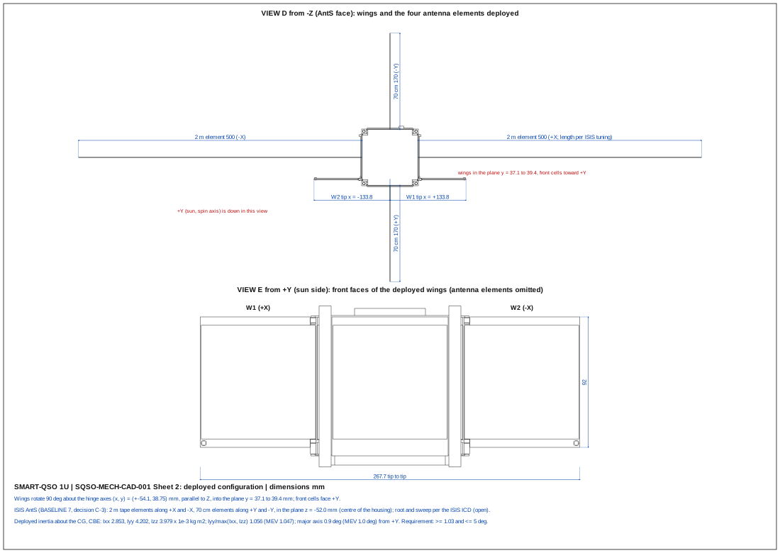
An ISIS AntS unit on the −Z face with four tape monopoles: two for 2 m (≈ 0.5 m) along ±X and two for 70 cm (≈ 0.17 m) along ±Y. They deploy after the wings.

SQSO-BL-001 §7 SQSO-MECH-CAD-001 §5.2

Attitude control

Magnetorquer rods, a magnetometer, the panel photodiodes as sun sensors and a MEMS gyro. B-dot detumble, then a spin of 8°/s that keeps the wings' side toward the Sun. No reaction wheels and no propulsion.

SQSO-BL-001 §8

Navigation

A duty-cycled GNSS receiver (SkyFox piNAV-NG/FM) gives the operator ephemeris the launch provider requires within 24 hours of first contact.

SQSO-BL-001 §6

Thermal

No fan or active cooling: a ≈ 207 Ω battery heater that switches on below +5 °C and off above +9 °C, and a heat spreader from the Jetson to the frame.

SQSO-BL-001 §8

CAD drawings

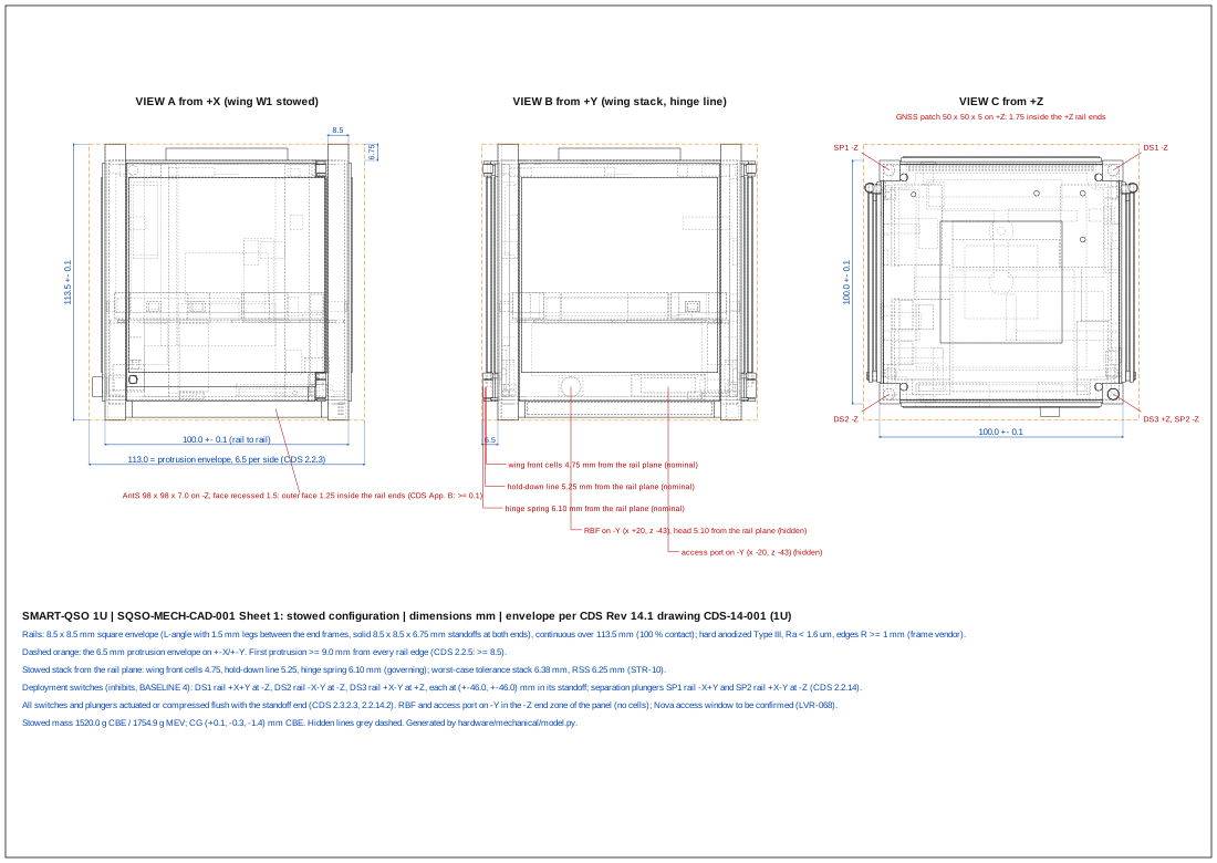
Hidden-line projections of the parametric CAD model (SQSO-MECH-CAD-001 version D), generated by hardware/mechanical/model.py. They are layout drawings for review, not manufacturing drawings. SQSO-MECH-CAD-001 §7

CAD sheet 1: three views of the stowed 1U CubeSat with the CubeSat Design Specification envelope, rail dimensions, the 6.5 mm protrusion envelope, the internal board stack, and the locations of the deployment switches, separation plungers, remove-before-flight pin and access port.
Sheet 1, stowed: three views with the CDS envelope, the rails, the protrusion envelope and the switches. Open the drawing for full size.
CAD sheet 2: the deployed configuration seen from the antenna face and from the sun side, with the two solar wings spanning 267.7 mm tip to tip and the antenna element extents.
Sheet 2, deployed: wing and antenna extents, 267.7 mm tip to tip across the wings.

STEP models of both configurations are in hardware/mechanical.

How far the design has got

Each board is captured as code (SKiDL) with selected parts, a netlist, a bill of materials with derating and an electrical rules check; the mechanical design is a CAD model with interference checks and a finite-element model. SQSO-REV-CDR-002 §5

Design completion (CDR report §5)
ItemDocumentWhat existsKey results
EPS and safety boardSQSO-EPS-BRD-001 G742 placements, ERC 0; trackers, battery management (BQ76952 with the BQ771806 backup protector and F3 on the battery sense board), current-limited rails, four independent burn lines, DS1–DS3 inhibits, one-shot end-of-life disconnect, recharge lockout, EPS controllerBurn 0.67 A nominal one resistor at a time; storage drain 7.8 µA typical, 13.8 µA worst; diverse pack fuses F0A/F0B/F0N (C-16); every timing worst case with the X7R cold change
OBC boardSQSO-OBC-BRD-001 E385 placements, ERC 0; STM32L4R5, window-watchdog supervisor (440 nF C0G), RTC, two FRAMs, gyros, sun-sensor ADC, magnetorquer drivers; magnetometer board A2; access-port board A3Every pin one function (SQSO-ICX-001 D); IWDG refreshed with the supervisor kick, IWDG first by 1.5 s; magnetometer at the +Z end
RF boardSQSO-RF-BRD-001 F330 parts (300 fitted), ERC 0; CC1200 receiver, TNC MCU, LMX2571 exciter with readback, PA, filters, nickel-silver shield, MMCX portsDesense ≤ 0.44 dB; receive noise 552–603 K (L106 18 nH); carrier-detect and receiver-health lines; PA cold characterisation VI-RFB-14; CC1200 TX-OFF leakage VI-RFB-16
Jetson carrierSQSO-JET-BRD-001 E137 placements, ERC 0; 5 V buck and eFuse, sequencing, translated UART, NVMeModule capped at 6.5 W (+6.5–10 % to 8 W); gyro window; 2.0 mm, 6 layers; module cold limits governed by the −15 °C power-on gate and V-THM-8
InterconnectSQSO-ICX-001 DMaster pin allocation and harness listEvery firmware pin change implemented (OBCB-02)
HarnessSQSO-HAR-001 2.0210 conductors, 61 zones in the CAD frame, calculations script, wire listDerating ≤ 60 % normal; gold terminals; four D-200-82 splices, 28 AWG leads on solder tabs; 85.6 g
MechanicalSQSO-MECH-CAD-001 BCAD (STEP), harness zones, splice and tab envelopes, interference checks (529 / 523 pairs); hinge model with the line spring; shell FE (eight cases)First mode 170 / 162 Hz; lowest strength margin +0.97 (+0.86 MEV); board fatigue +0.42 to +0.72 (+0.14 MEV); inertia ratio 1.056 / 1.047 with the C-13 ballast; mass 1.755 kg MEV (+14.0 %)
PartsSQSO-MFG-003 C, SQSO-MFG-002 GTemperature-grade audit of all 443 flight BOM lines; every line orderableFive parts below −40/+70 °C, each covered by design, qualification or a dated vendor action (P3T-02 to P3T-04, P3T-09)
Flight softwareSRS 1.12; software/rustPassivation, stored housekeeping, acknowledgements, receiver supervision, memory-upset handling (round 2); pin map and drivers, AntS temperature gate and transmitter hold, PTT watch, closure-panel fixes (round 3)622 Rust tests, 56 C suites; safety-critical gate 32 files at 100 % / 100 %; stack 5,812 / 8,192 B; full mission simulation 0 anomalies in 50 checks (SQSO-SIL-001 G §7)
Board firmwareSQSO-SRS-TNC-001 B, SQSO-SRS-EPSC-001 BRequirements for the RF board TNC firmware (67) and the EPS controller firmware (62), hazards SW-HAZ-014 to -017, schedule tasksToolchains for PI ratification (DA-22): Rust no_std (TNC), C11 MISRA (EPS controller)

What the design does not yet have: PCB layouts (SE-24, scheduled after the independent PDR), an engineering model, and the vendor-drawing confirmations listed as verification items (connector mated heights, gold part numbers, fuse ratings, outgassing data).

Margins on mass, power, structure, links and more: engineering.